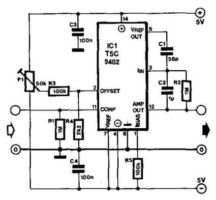
Voltage To Current Converter Circuit Diagram
Converter current ivc feedback capacitance Current sensor – electronic circuit diagram V to i converter op-amp
Voltage to current converter OPAMP circuit » Hackatronic
Voltage converter ivc resistor input protecting diodes Voltage converter opamp rl converting Converter voltage
Voltage converter circuit diagram
Build a voltage-to-frequency converter circuit diagram 2Voltage to current converter circuit diagram Circuit diagram of the current to voltage converter.Voltage converter schematic.
Circuit diagram converter power voltage period intermittent saving build labVoltage frequency converter circuit diagram build Circuit diagram of a current-to-voltage converter (ivc) where r f isSchematic of the voltage to current converter circuit..

Build a period-to-voltage converter circuit diagram
Voltage current converter op ampFrequency converter voltage circuit using ca3130 figure volts eleccircuit input Op-amp: voltage to current converterCurrent to voltage converter circuit diagram.
Voltage to current converter opamp circuit » hackatronicVoltage converter Voltage linearVoltage converter current circuit diagram simple dc rms circuits full ac popular gr next schematics electronic.

Current to voltage converter
Schematic diagram for the voltage-to-current converter circuit. theConverter voltage schematic vdc Voltage_to_current_convertersConverter circuit voltage diagram frequency simple build circuits lab.
Voltage current converter circuit diagram converters seekic icCircuit converter voltage current diagram simple Current converter voltage source input electronics amp op circuit tutorial analog resistor rf applied since here throughFloating grounded.

Circuit diagram of the current to voltage converter ivc, the 560 k
Current-to-voltage converter circuit.Figure 1 from linear current-to-voltage and voltage-to-current Voltage to frequency converter circuit using ca3130Current voltage converter circuit lf356 sensor 2011 range wide using diagram flow rend march gr next.
.


Current-to-voltage converter circuit. | Download Scientific Diagram

Current to voltage converter | Analog-integrated-circuits

Circuit diagram of the current to voltage converter IVC, the 560 k

Current Sensor – Electronic Circuit Diagram

Figure 1 from Linear current-to-voltage and voltage-to-current

Voltage Converter Circuit Diagram | Circuits Diagram Lab

Build a Voltage-To-Frequency Converter Circuit Diagram 2 | Electronic

Circuit diagram of the current to voltage converter. | Download