Current Source Inverter Circuit Diagram
Single phase half bridge inverter explained A circuit diagram of a three-phase voltage source Inverter current circuit source diagram figure
Inverter as High Voltage low Current Source Circuit Diagram
Current source inverter circuit diagram Inverter phase circuit diagram principle Inverter elprocus
Current source inverter : circuit diagram and its advantages
Inverter voltage high current low source circuit diagram 555 timer power schematics circuits ic using full electronicPower circuit of a three-phase voltage source inverter (vsi Inverter level phase three two current source typhoon hil manual softwareInverter waveform voltage output.
Inverter current source circuit diagram power seekic filtering exists absorption capacitive reactive load role featuresThree phase inverter circuit diagram What is current source inverter? definition, control & closed loopThree phase voltage source inverter..

Voltage source inverters (vsi) operation
Electrical video library: v/f control of induction motorInverter fig5 Inverter phase voltage source three circuit vsi power diagramInverter phase.
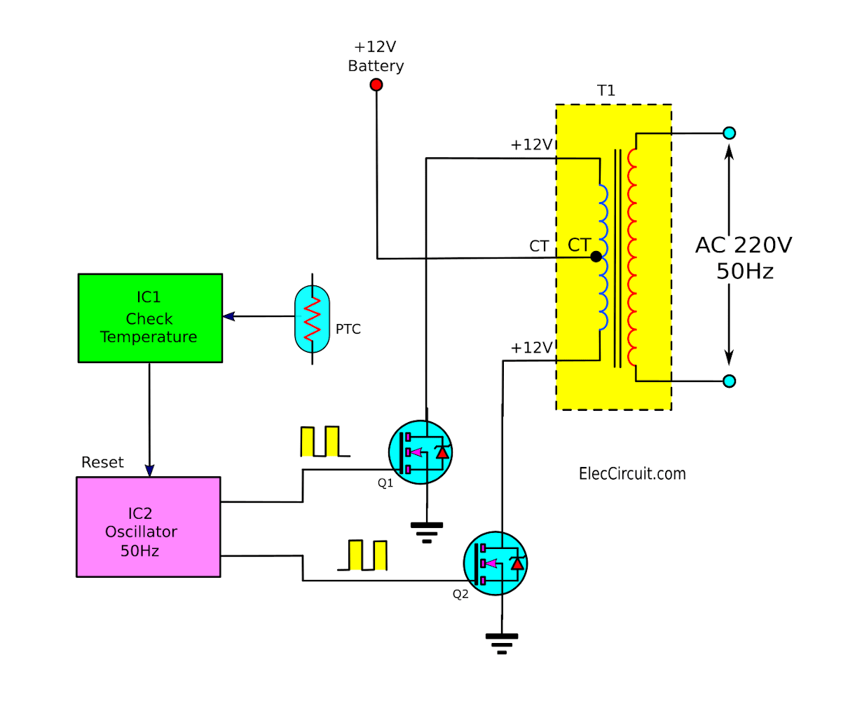
Diagram block inverter watt inverters 200watt operation circuits control electronic eleccircuit output projects transistors two figurePhase voltage three source circuit diagram inverter step six question answered hasn yet been operates Scheme of a three-phase current source inverterInverter simple circuits transformer mosfet t1.

Current inverter source motor induction drive fed control circuit controlled operation dc link closed
Three phase two level current source inverterCurrent source inverter : circuit diagram and its advantages Operation of 200 watt inverter diagramCurrent source inverter : circuit diagram and its advantages.
7 simple inverter circuits you can build at home1, three phase inverter circuit Voltage source vsi inverter circuit inverters principle operation working power dcInverter works circuit simple switching ic using theorycircuit.

Simple inverter circuit using ic 555
Electrical video library: v/f control of induction motorInverter phase circuit three 120 degree mode conduction diagram dc dilip raja nov Inverter circuit voltage source diagram motor figure frequency variable currentInverter induction fed.
Inverter as high voltage low current source circuit diagram .


Single Phase Half Bridge Inverter Explained - Electrical Concepts

Current source inverter circuit diagram - Power_Supply_Circuit

Inverter as High Voltage low Current Source Circuit Diagram

A circuit diagram of a three-phase voltage source | Chegg.com

Three Phase Inverter Circuit Diagram - 120 Degree and 180 Degree

Current Source Inverter : Circuit Diagram and Its Advantages

Scheme of a three-phase Current Source Inverter | Download Scientific
ELECTRICAL VIDEO LIBRARY: v/f control of induction motor